1. Preface
1. Preface
1. Preface
This course is offered by the School of Electronics and Information Technology (School of Microelectronics) at Sun Yat-sen University.
This is a practical course where you can learn a lot of things. Since the provided lab board is different from the one at hand, modifications were made to the code to adapt it to my board.
The purpose of this project is, firstly, to complete the six labs and the course design as part of the coursework submission. Secondly, it aims to provide a reference for those who may use the same board in the future (as I have noticed that this board is still quite popular among FPGA buyers).
1.1 Software and Hardware Environment
- Windows 11
- Vivado 2024.1
- Chip: xc7z010clg400-1
AX7010 Documentation
- Schematic Diagram (This is quite important as it provides definitions for all the pins)
- PCB Design Guide
- Zynq-7000 Data Sheet
- XADC User Guide
- Technical Reference Manual (TRM)
- Software Development Guide
- Package Pinout Guide
Board:
ZedBoard Documentation
- ZedBoard Schematic Diagram
- ZedBoard Zynq-7000 ARM FPGA Advanced Manual
- ZedBoard User Hardware Manual
- ZedBoard Schematic
- ZedBoard Getting Started Guide
- Baseboard Schematic Diagram
- Core Board Schematic Diagram
- Hands-on Manual (Step-by-Step)
ZedBoard:
1.2 Precautions
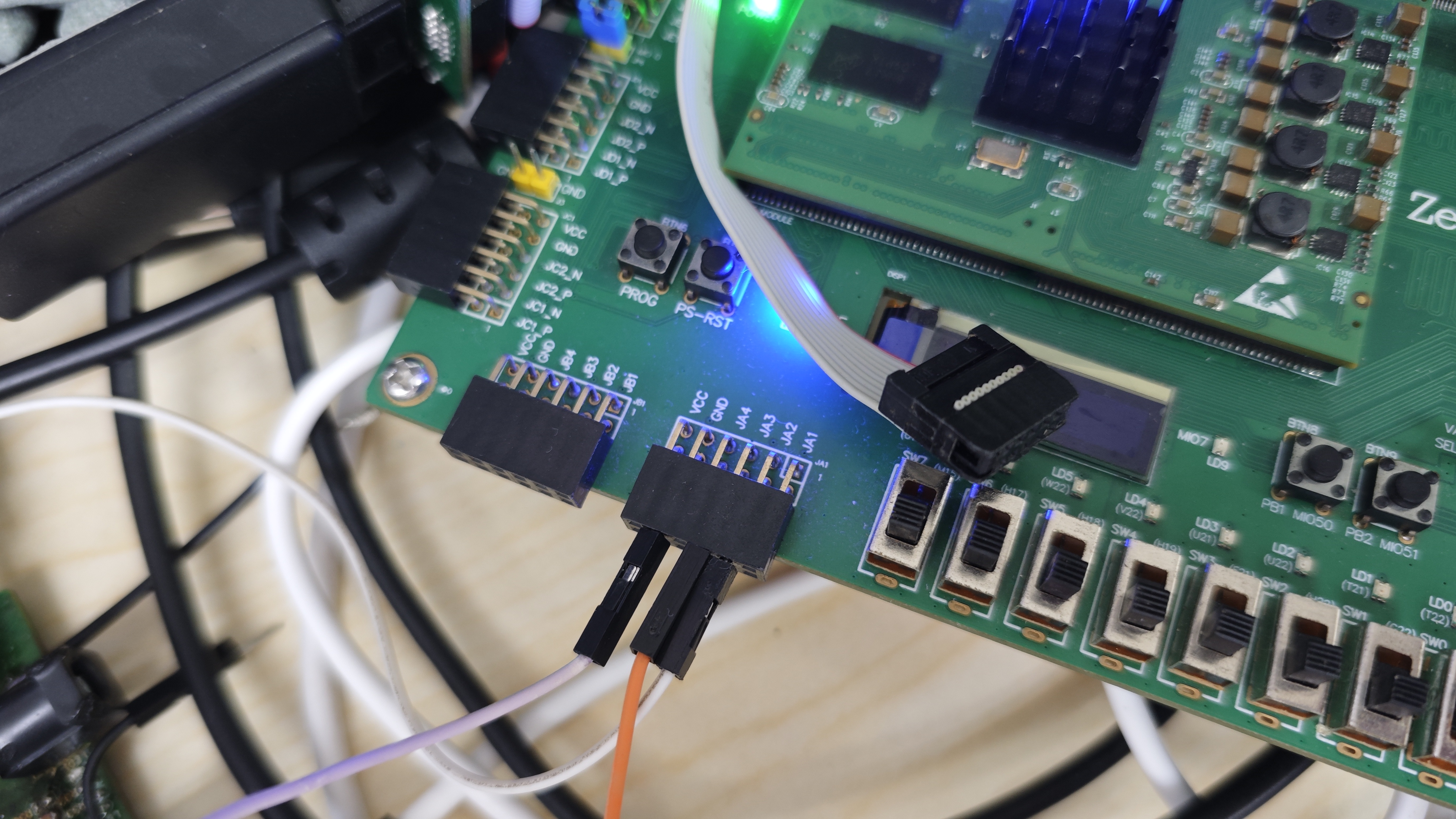
For this set of experiments, except for Experiment 1, the remaining experiments (2, 3, 4, 5, 6) all require the use of UART. From the XDC file, it can be determined that the UART is mapped to pins JA2 and JA3, so the UART connected to the top-left USB is not used (this is the PS-configured UART, not the PL-configured UART).
Correct UART connection:
Location is in the lower-left corner of the board, and the IO pins can be identified by the silk screen markings.